Transforming Technologies Data Terminal TC18 User's Manual
Data Terminal TC18
Table of contents
INTRODUCTION................................................................................................ 3
PACKAGE CONTENT......................................................................................... 3
INSTALLATION................................................................................................... 3
-
Checks....................................................................................................... 3
-
Overview.................................................................................................... 4
-
Optional Extensions................................................................................... 5
-
Installation.................................................................................................. 7
-
Getting Started........................................................................................... 7
OPTIONAL SETTINGS.........................................................................................7
OPERATION.........................................................................................................8
-
Manual IP-Address Configuration............................................................. 10
-
Extended Configuration............................................................................. 11
-
Firmware Update....................................................................................... 12
DATA EXPORT INTERFACE...............................................................................13
-
Interface 1 - RAW...................................................................................... 13
-
Interface 2 - CSV........................................................................................14
-
Interface 3 - DatatermD............................................................................. 15
TECHNICAL DATA..............................................................................................16
CONSUMABLES.................................................................................................16
WASTE DISPOSAL............................................................................................ 16
Introduction
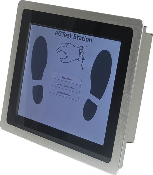
The "Data Terminal 2", is a modular system for recording and processing Personnel Grounding Tester's test data. A basic system consists of:
- PGT120.COM (1)
- and Data Terminal (2).
Test data can be stored for one month inside the device. The data can be retrieved by a web browser from any computer when connected to a network.
Test data can be imported to Time Attendance or Access Control systems via network interface.
The user identification can be made with many USB HID input devices (RFID, barcode, magnetic card, keyboard)
Multiple devices can be networked together and managed by one server component. User data and measurement data can be managed central.
An open user- and measurement data interface allows end-user customization
Remote PC functions when connected to network:
- List of test data with coloured marking of failed tests
- Printed test results list
- WEB-interface for easy configuration
- German and English support
Package Content
- Data Terminal Part No: PGT120.COM.DT
- Power supply
- User's manual (German/English)
Note: A Personnel Grounding Tester PGT120.COM (1) (Part No. 7100.PGT120.COM) is required for operation.
Installation
Checks
- Check the package content and make sure that no parts have been damaged during transportation
- Compare the information on the instrument label with the information on the delivery note
- Check that the voltage printed on the power supply complies with your local mains voltage
Overview

Optional Extensions
Label Printer (1)
Label printing for passed tests with test results and measurement values.
| Type | SLP650 |
| BUS | USB 2.0 |
| BUS-ID | 0619:0502 / 0619:0126 |
| Part No | 7100.PGT120.COM.D.2 |

T/H-Sensor
The current temperature and the relative humidity is recorded if the T/H-Sensor is connected.
| Type | EL-USB-RT |
| BUS | USB 1.1 (50 mA) |
| BUS-ID | 1781:0EC4 |
| Part No | 7100.PGT120.TEST.10 |

Relay Module
The relay module provides two different output channels.
Output 1: One second trigger for passed shoe test.
Output 2: One second trigger for passed wrist strap test.
Contact ratings: 0,3A at 30V AC / 1A at 24V DC
| Type | USB-Mini-REL2 |
| BUS | USB 2.0 / USB 1.1 (100mA) |
| BUS-ID | 0403:6001 |
| Part No | 100.PGT120.TEST.12 |

Beacon (Visual Signal Indicator)
Red / green / yellow - visual indication of the access clearance
| Manufacturer | Delcom Products Inc. |
| Type | USB HID Visual Signal Indicator RGY 904007 (Gen II) |
| BUS | USB 2.0 / USB 1.1 (100mA) |
| BUS-ID | 0FC5:B080 |
| Part No | 7100.PGT120.TEST.13 |

Input Device
The User-ID is queried if a valid input device was connected.
Possible input devices are: RFID-readers, Barcode scanners, Magnetic stripe readers and Keypads.
Valid input devices are devices which identify themselves on the USB-Bus as Human Interface Device (HID). Only one HID-Device can be connected at the same time. The maximum provided power for the device is 500mA. The expiration time for the User-ID is 10 seconds.

USB-HUB (passive)
To connect multiple optional extensions, a USB-HUB with USB 2.0 / USB 1.1 specification is required. To connect the within this document listed devices a passive HUB (without additional power supply) is sufficient.
| Type | UA0139 |
| BUS | USB2.0 / USB1.1 |
| BUS-ID | A140:0101 |
| Part No | 7100.PGT120.TEST.16 |

Interface Connection Example:

Installation
Connect the PGT120.COM serial interface to the RS232 socket of the TouchScreenMonitor TC18 Four USB ports are available on the Data Terminal TC18. Connect the Input device directly to one USB port. Connect the optional extensions to the other USB ports. For multiple extensions use a USB-HUB as distributor.
If desired, connect the Ethernet cable to ETH.
Connect the power supply to the Data Terminal.
 |
Use only the original power supply. Rebooting is required to activate new connected USB devices. |
Getting Started
The terminal is ready within 50 seconds after plugging-in the power supply. If the Ethernet cable is connected, the device tries to configure its network by DHCP. Therefore a DHCP-server should be available within the network. A label indicating the assigned IP Address will be printed on system start-up if the label printer is connected. The IP-Address is displayed on the LCD if connected.
System clock can be set by DHCP as well (042 timeserver).
The configured DHCP hostname will be sent to the DHCP server if available. If DHCP configuration fails the default IP-Address 192.168.1.1 will be used.
It is possible to enter a different IP-Address manually. However this is not recommended because the device has no reset capability and would not be accessible any more in case of false configuration. Read section "ManUal IP-Address ConfigUration" for this. Alternatively you could prefix a router with required functionality. Entering a fixed IP-Address will deactivate DHCP.
To configure the Data Terminal enter the assigned IP-Address into your browser's URL-filed. The first access opens the configuration page without asking for a password.
Adjust and safe the settings to continue.
Important settings:
- The Terminal's time zone, date and time must first be set in System settings.
- Measurement data - "footwear in series" must be set according to the connected COM DIP- switches.
After saving the settings you find the two optional sections Network and Advanced in the Configuration menu.
Optional settings:
- If desired you can configure a fixed IP-Address in section Network.
- Settings for User data synchronization are available in section Advanced.
Operation
Configuration
Administration password is required for configuration. The default login is User: admin Password: admin. The user can change the password.
System settings
- Company name or independent text. This will be printed on the first line of each label. The user ID can be printed instead, if user identification is enabled and this field is
- WEB-interface language
- Set the date
- Set the time
- Select current time zone
- Print assigned IP-Address after each system start-up
- Reboot the terminal
- Change the configuration password
- System reset (measurement data and settings will be erased)
- Firmware upload
- DHCP hostname configuration
Measurement data
- Select amount of records to be viewed in measurement data view
- Footwear in series (this must correspond to the DIP-switch setting of the PGT120.COM)
- Enable or disable coloured marking of failed test
- Download measurement data as CSV file
- Clear all measurement data
Label printer
- Enable or disable the Label printer. Select "ID<99" to print the label only if the entered user ID has less than three characters.
- Printer and paper selection
- Configure printing system
- Delete pending print jobs

Test data
Test data view is the main entry page. A configurable number of records are displayed, including test data, date, time and test result. Measurement data view is updated every 20 seconds.
The current temperature and the relative humidity is recorded if the T/H-Sensor is connected.
If the Input Device is connected, the ID shows up and measurements without ID will be invalid.
If the ID is linked to a username, then the username is displayed instead.

System Info
- Display of software versions
- System time
- Device's IP and MAC-address
- Last measurement poll-time
- Last sync of user data and amount of records
- Connected USB devices and, if available their USB-ID

History
One month's test data storage is separated for each day. Use the browser's printing function to print.

Manual IP-Address Configuration
Make sure you have an arbitrary USB memory stick (Mass Storage Device) ready to use. This is required to reactivate default settings in case of misconfiguration.
- Log into the configuration page with your username and password.
- Select Configuration -> Network.
- Enter the desired IP-Address and associated Netmask carefully.
- If required, a gateway address can be
- Save the settings and reboot the device with Configuration -> Reboot.
Recovery
If you've entered an incorrect IP-Address, the device is not accessible within the network any more.
To rectify the faulty settings you've to connect a USB memory stick and reboot the device. With connected memory stick the device will boot with default network settings according to section "Getting started". You can follow the instructions "Getting Started" to make the changes and reboot the device without memory stick again.
Extended Configuration
Advanced
Advanced settings for measurement data retrieval and user data synchronization are available here.
It is recommended to use HTTPS instead of HTTP as secure communication for measurement and user data transfer. You can additionally define a password for the communication.
- Access password: Password for the connection
- User-ID check: Access for only persons defined in the user database (no anonymous access)
- Delete the user database
- Upload user data via CSV
The file must contain the column ID and Name.
Lines with # at the beginning are ignored. Use Semicolon or Tab-Stop as Separator and file extension TXT or CSV. Character coding is UTF-8
- Download user data as TEXT/CSV file
- Relay trigger time settings
- Signal light timing
- Signal light buzzer settings

MS-Excel view:

Stored as CSV or TXT file:

Special Function:
Service-access without measurement validation
Users whose names are marked with a leading asterisk "*" are allowed to pass even if the measurement values are out of range. The beacon will indicate “yellow” instead of “green” and no label will be printed.
Screen Settings
Upload custom videos to replace the built-in instruction video and demonstration video. The lengt of the video file should be app. 20 seconds. The demonstration video is preferred to be without audio.
Video file format
| Aspect | 800 x 600 px |
| Bitrate | 6000 kbit/s |
| Videocodec | msmpeg4v2 |
| Framerate | 15 Hz |
| Audiocodec | pcm_s16le |

- Delete all custom videos to reset to standard video
- Enable custom videos to disable the standard videos and use the custom videos if If no custom video was uploaded the video function is disabled.
- Privacy mode disables the Personnel data in the measurement view.
Firmware Update
Use Configuration -> Firmware upload -> Search to select the appropriate BIN file. Only newer versions can be installed, downgrade is not possible. Use the Save settings button on the bottom of the page and wait until the update has finished (at least 3 minutes).
|
Do not disconnect the power supply during the update. |
Data Export Interface
Test data can be polled by Time Attendance or Access Control systems via Ethernet Interface. A HTTP-GET query returns the data in [Content-Type: text/plain Charset: utf-8].
Export data is erased after each poll.
Interface 1 - RAW
URL
http://<ip-address>/cgi-bin/pgt120-data.cgi?fetch=1
Records:
2011-01-19|16:53||||||no data||
Record:
2011-01-19|16:53||||2786|256|UserID missing|20.1|34.0
Several Records:
2011-01-19|16:53||||2786|256|UserID missing |20.1|34.0
2011-01-19|16:54||||OVR|258|Wrist strap Hi-Fail; UserID missing |20.1|34.0¶ 2011-01-19|16:55||||2786|OK||20.1|34.0
Meaning:
date|time|rsg|rsl|rsr|rhg|erg|msg|id|tmp|hum
| Field | label | Description | Format |
| 1 | date | Date of Measurement | 2011-01-19 |
| 2 | time | Time of Measurement | 16:53 |
| 3 | rsg | Result Shoes in Series (kOhm) | Integer |
| 4 | rsl | Result Shoe left (kOhm) | Integer |
| 5 | rsr | Result Shoe right (kOhm) | Integer |
| 6 | rhg | Result Wrist Strap (kOhm) | Integer |
| 7 | erg | 'OK' or ErrorCode | Number or String (see below) |
| 8 | msg | Terminals Message text | String (see below) |
| 9 | id | User-ID | RFID-Reader data (Filter: ASCII 32-127, max. 30 digits) |
| 10 | tmp | Temperature at measurement | 20.1 |
| 11 | hum | Humidity at measurement | 34.0 |
| Error | Code | Message text (EN / DE) |
| erg | msg | |
| OK | = | '' |
| 0 | = | no data |
| 1 | = | Wrist strap Lo-Fail / Handgelenkband Lo-Fail |
| 2 | = | Wrist strap Hi-Fail / Handgelenkband Hi-Fail |
| 4 | = | Left shoe Lo-Fail / Linker Schuh Lo-Fail |
| 8 | = | Left shoe Hi-Fail / Linker Schuh Hi-Fail |
| 16 | = | Right shoe Lo-Fail / Rechter Schuh Lo-Fail |
| 32 | = | Right shoe Hi-Fail / Rechter Schuh Hi-Fail |
| 64 | = | Measuring voltage failure / Fehlerhafte Messspannung |
| 128 | = | Unknown / Unbekannt |
| 256 | = | UserID missing / UserID fehlt |
| 512 | = | Unauthorized user / Unberechtigt |
| 1024 | = | Service access / Service Zugang |
| -10 | = | Button released too early / Tastblech zu früh losgelassen |
Readings
rsg,rsl,rsr,rhg
| OVR | = | Measuring range exceeded / Messbereich uberschritten |
| UNR | = | Measuring range undercut / Messbereich unterschritten |
Interface 2 - CSV
Exported data in CSV can directly be opened with spreadsheet programs, i.e. MS-Excel.
Differences to Interface 1:
- Field separation character is Semicolon
- All fields are quoted with double quotes
- If no data is present, then erg is set to "0" and msg is set to "no data"
- Number code (Button released too early) "-10" replaced by 'MTF' (Measuring Time Failure)
- If erg is "OK" then the field msg is set to "OK" as well
- OVR and UNR is suppressed, this filed is empty for over-range or under-range conditions
URL:
http://<ip-address>/cgi-bin/pgt120-data.cgi?fetch=2
0 Records:
"2011-01-19";"16:53";"";"";"";"";"0";"no data";"";"";""
1 Record:
"2011-01-19";"16:53";"";"";"";"2786";"256";"UserID missing";"";"20.1";"34.0"
Several Records:
"2011-01-19";"16:53";"";"";"";"2786";"256";"UserID missing ";"";"20.1";"34.0"
"2011-01-19";"16:53";"";"";"";"";"258";"Wrist strap Hi-Fail; UserID missing ";"";"20.1";"34.0"
"2011-01-19";"16:53";"";"";"";"2786";"OK";"OK";"";"20.1";"34.0"
Meaning:
date|time|rsg|rsl|rsr|rhg|erg|msg|id|tmp|hum
| Field | label | Description | Format |
| 1 | date | Date of Measurement | 2011-01-19 |
| 2 | time | Time of Measurement | 16:53 |
| 3 | rsg | Result Shoes in Series (kOhm) | Integer |
| 4 | rsl | Result Shoe left (kOhm) | Integer |
| 5 | rsr | Result Shoe right (kOhm) | Integer |
| 6 | rhg | Result Wrist Strap (kOhm) | Integer |
| 7 | erg | 'OK' or ErrorCode | Number or String (see below) |
| 8 | msg | Terminals Message text | String (see below) |
| 9 | id | User-ID | RFID-Reader data (Filter: ASCII 32-127, max. 30 digits) |
| 10 | tmp | Temperature at measurement | 20.1 |
| 11 | hum | Humidity at measurement | 34.0 |
| Error | Code | Message text (EN / DE) |
| erg | msg | |
| OK | = | '' |
| 0 | = | no data |
| 1 | = | Wrist strap Lo-Fail / Handgelenkband Lo-Fail |
| 2 | = | Wrist strap Hi-Fail / Handgelenkband Hi-Fail |
| 4 | = | Left shoe Lo-Fail / Linker Schuh Lo-Fail |
| 8 | = | Left shoe Hi-Fail / Linker Schuh Hi-Fail |
| 16 | = | Right shoe Lo-Fail / Rechter Schuh Lo-Fail |
| 32 | = | Right shoe Hi-Fail / Rechter Schuh Hi-Fail |
| 64 | = | Measuring voltage failure / Fehlerhafte Messspannung |
| 128 | = | Unknown / Unbekannt |
| 256 | = | UserID missing / UserID fehlt |
| 512 | = | Unauthorized user / Unberechtigt |
| 1024 | = | Service access / Service Zugang |
| MTF | = | Button released too early / Tastblech zu früh losgelassen |
Interface 3 - DatatermD
Special communication format for DatatermD service.
Differences to Interface 1:
- If no data is present, then erg is set to "0" and msg is set to "no data"
- If erg is "OK" then the field msg is set to "OK" as well
- OVR and UNR is suppressed, this filed is empty for over-range or under-range conditions
URL
http://<ip-address>/cgi-bin/pgt120-data.cgi?fetch=3
Records:
2011-01-19|16:53|||||0|no data|||
Record:
2011-01-19|16:53||||2786|256|UserID fehlt||20.1|34.0
Several Records:
2011-01-19|16:53||||2786|256|UserID fehlt||20.1|34.0
2011-01-19|16:54||||OVR|258|Handgelenkband Hi-Fail; UserID fehlt||20.1|34.0¶ 2011-01-19|16:55||||2786|OK|OK||20.1|34.0
Meaning:
date|time|rsg|rsl|rsr|rhg|erg|msg|id|tmp|hum
| Field | label | Description | Format |
| 1 | date | Datum der Messung | 2011-01-19 |
| 2 | time | Uhrzeit der Messung | 16:53 |
| 3 | rsg | Messwert Reihenmessung (kOhm) | Integer |
| 4 | rsl | Messwert Schuh Links (kOhm) | Integer |
| 5 | rsr | Messwert Schuh Rechts (kOhm) | Integer |
| 6 | rhg | Messwert Handgelenkband (kOhm) | Integer |
| 7 | erg | 'OK' oder Fehlercode | Zahl oder String s.u. |
| 8 | msg | Meldetext des Terminals | String s.u. |
| 9 | id | Benutzer-ID | Zeichenkette vom RFID-Leser (Filter: ASCII 32-127, max. 30 Stellen) |
| 10 | tmp | Temperatur bei Messung | 20.1 |
| 11 | hum | Feuchtigkeit bei Messung | 34.0 |
| Error | Code | Message text (EN / DE) |
| erg | msg | |
| OK | = | '' |
| 0 | = | no data |
| 1 | = | Wrist strap Lo-Fail / Handgelenkband Lo-Fail |
| 2 | = | Wrist strap Hi-Fail / Handgelenkband Hi-Fail |
| 4 | = | Left shoe Lo-Fail / Linker Schuh Lo-Fail |
| 8 | = | Left shoe Hi-Fail / Linker Schuh Hi-Fail |
| 16 | = | Right shoe Lo-Fail / Rechter Schuh Lo-Fail |
| 32 | = | Right shoe Hi-Fail / Rechter Schuh Hi-Fail |
| 64 | = | Measuring voltage failure / Fehlerhafte Messspannung |
| 128 | = | Unknown / Unbekannt |
| 256 | = | UserID missing / UserID fehlt |
| 512 | = | Unauthorized user / Unberechtigt |
| 1024 | = | Service access / Service Zugang |
| -10 | = | Button released too early / Tastblech zu früh losgelassen |
Technical Data
| Cooling | Fanless |
| Interface | 4×USB 2.0, 1 x COM RS232 1×VGA/HDMI/RJ45/Audio OUT/MIC IN/POWER DC |
| Power supply | AC 100–240V 50-60Hz / DC 12V, 5A |
| Power consumption | ≤45W |
| Housing | Aluminum, silver |
| Mounting | Front-panel and VESA 75×75mm / 100×100mm |
| Front-panel | IP65 |
| Operating conditions | 0°C to 50°C / up to 65% r.H. |
| Dimensions | 288x231×58 mm |
Consumables
Following consumables are available for the Label Printer (3):
Self-adhesive labels - colour: white. Type: SLP-STAMP2 (36x67mm) Part No: 7100.PGT120.COM.D.3 Self-adhesive labels - colour: orange. Type: SLP-1OLB (28x89mm) Part No: 7100.PGT120.COM.D.4
Waste Disposal
The instrument is a category 9 product (monitoring and control instrument) in accordance with ElektroG (German and Electronic Device Law). This device is not subject to the RoHS directive. We identify our electrical and electronic devices in accordance with WEEE 2012/96/EU and EletroG with the symbol shown to the right per DIN EN 50419. These devices may not be disposed of with the trash.

If you use batteries or rechargeable batteries in your instrument or accessories which no longer function properly, they must be duly disposed of in compliance with the applicable national regulations. Batteries or rechargeable batteries may contain harmful substances or heavy metal such as lead (PB), cadmium (CD) or mercury (Hg).
The symbol shown to the right indicates that batteries or rechargeable batteries may not be disposed of with the trash, but must be delivered to collection points specially provided for this purpose.