Transforming Technologies Ranger NET Network Ready Constant Monitor Model CM2815 User's Manual
Ranger NET Network Ready Constant Monitor Model CM2815

Instruction Manual
Contents
Description
| CM2815 | 1 |
| Features | 1 |
Installation
| Installation Instructions | 2 |
| Installation Diagram | 3 |
Operation
| Wrist Strap Indications | 5 |
| Mat Indications | 6 |
| GND monitor Indications | 6 |
| Maintenance | 6 |
| Specifications | 7 |
| Service and Warranty | 9 |
Ohm Metrics Resistance Monitor: CM2815
The Ohm Metrics' CM2815 Series dual conductor workstation moni- tor provides continuous monitoring of resistance for two wrist straps and two mat. The status’ are displayed using tricolor LED’s on the front panel of the monitor and abnormal levels trigger an alarm to inform operators on the line. Utilizing low-voltage, resistive loop technology, and dual conductor ground products, the CM2815is an extremely sensitive and reliable ground monitoring for use in highly critical areas.
The CM2815 is network ready and can easily be connected to other workstation monitors and a computer using the high speed network router, CM2800-H. The host computer can be transformed into a command center with the software CM2800-BOSS SEE, a central monitoring program that shows real time grounding results and al- lows for adjustment of alarm parameters of up to 4096 workstations. An entire assembly line’s ESD protection can be remotely monitored and adjusted with one computer.
Features:
- Monitors two wrist straps, and work
- Network Ready
- Ultra-Low voltage for highly critical
- Uses Dual Conductor Wrist Straps
Operation
The CM2815 monitors the grounding functions of a workstation and alerts users when levels are out of the set range. The CM2815 has the capabilities to monitor the resistance of two wrist straps/Operators and two Work surfaces.
Alerts
If any parameters exceed the preset high limits, the corresponding LED on the front panel of the monitor will change color from green (OK) to red (high warning) to indicate the abnormal situation. If the resistance is below preset low limit, the LED color will be yellow (low warning).
An audible alarm will sound, in addition to the corresponding LED indi- cator when the resistance is in an abnormal state. For instant differen- tiation, a single beep will sound if the abnormal situation occurs on “Station 1” whereas a double beep sound for “Station 2”.

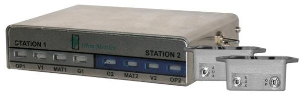
(LED indicators illustration of CM2800 front panel.)
- “OP 1” and “OP 2” - Grounding resistance of operators
- “V1” and “V2” - Induced voltage on operator - disabled on CM28015
- “MAT1” and “MAT2” - Grounding resistance of work surfaces
- “G1” and “G2” - Grounding resistance of tools- disabled on CM28015
*The CM2815 only utilizes OP1, OP2, MAT1, MAT2
1. Operator Grounding
The operator is grounded when the dual conductor wrist strap is plugged in to the jack labeled “OP” of the grey remote. The correspond- ing LED label “OP” and “V” will be GREEN if levels are normal. If the any of these parameters exceed preset high limits, the corresponding LED will turn RED and alarm will sound. If the resistance of the wrist strap is below preset low limit, the LED will turn YELLOW and alarm. If the wrist strap is not plugged into the remote terminal jack, the LED’s of both “OP” and “V” will be off to indicate the stand-by mode. Factory set resistance limit is 1.8 megohm. Default Voltage limit is 2V .
Since the CM2815 is designed with a Ultra-Low Voltage circuit, the measurement voltage of the grounding resistance of the operator body can be as low as 0.2V. Therefore, when the low resistance of the wrist strap is measured, it may be affected by the small “Battery Effect” existed between the contact of the human body skin and the wrist-strap metal stud. To avoid this, the the low resis- tance measurement is disabled by default. If this measurement is turned on and the value is affected, you can reverse the direction of the wrist strap stud to resolve the influence.
If the cable connecting to a wrist strap remote is unplugged or sev- ered at either end, the monitor’s audible alarm will sound, and the corresponding “OP” LED will turn red.
Note: Each remote has two jacks labeled “OP” and “AUX”. The “OP” jack is monitored and “AUX” jack is not, but provides a grounding path for one more wrist strap. The status of “AUX” will not affect “OP”.
2. ESD Mat
The CM2815 can monitor the ground resistance of two dissipative surfaces. When the resistance is within acceptable limits, the LED labeled “MAT” will be GREEN. If it exceeds preset high limits, the LED will change to RED and an alarm will sound. Factory limits are set at 100 meg ohm.
Installation
Before you install your device, check for the items below:
- 1 - CM2815 workstation monitor
- 2 - Remote Jacks
- 1 - Power Supply
- 2 - Telephone Cables
- 3 - Grounding Cables: FM1515, FM1515CM, FM1515NR
Please carefully read the following instructions before proceeding with product installation.
- Install monitor in a location where alarm indicators will be visible and alarm will be audible to operator. Typical locations are under a workstation table or low
- Mount monitor securely in place with
- Install remote wrist strap terminals in a convenient location for Frequently remotes are mounted on the underside of the workbench nearest operators.
- Plug the telephone cable from the left remote to the OP1 on the back of
- Plug the telephone cable from the right remote to the OP2 on the back of
- Connect the bare end of the FM1515CM wire to the terminal on the back of the monitor labeled GND and connect to GROUND. See wiring
Mat Set Up: If no grounded ESD mats are to be monitored, connect a wire from both M1 and M2 terminals to the GND terminal on the back of the monitor and skip steps 8 and 9.
- Connect the FM1515NR cord from the first grounded Mat to the terminal on the back of the monitor labeled
- Repeat step 8 with an additional FM1515NR (not-included) if an additional mat is to be grounded. If not, connect a wire from M2 to GND to disable alarm function.
Note: The work surface mats have to be connected to the CM2815 with zero Ohm wire for proper mat monitoring operation. Using a wire with a 1M resistor may cause alarm. The FM1515NR is the pro- vided zero Ohm cord and more can be purchased from Transforming Technologies.
- Plug power supply into the PWR connector on the back of the monitor and into the power line.
Wiring Diagram

Calibration and Periodic Testing
Except the operator resistances, CM2815 never needs calibration. You can verify proper operation of the monitor by periodically test- ing the monitor with a resistance limit comparator box CM2800PV. Every CM2815 unit is calibrated at factory to meet the following criteria:
Operator Resistance: ±10%
Operator voltage: ±10%, or within 3 counts at 2V or less
Mat resistance: ±10%
Tool resistance: ±10%, or within 3 counts at 5Ω or less
If you need to calibrate the operator resistance of your CM2815 unit, please contact Transforming Technologies
Accessories
The CM2815 comes with a line of optional accessories:
- CM2800-D: Digital Display & External Control Module
- CM2800-H: Network Router
- CM2800-IMS: Real-time Central Monitoring Software
CM2815 Series Monitor Specifications
| Wrist Strap Low Resistance Alarm Limit | 1.8 meg ohm |
| Wrist Strap High Resistance Alarm Limit | 35 meg ohm |
| Mat (soft ground) Resistance Alarm Limit | 100 meg ohm |
| Typical Operator Voltage at 10M | |
| Imposed Voltage on Body | max 0.1V (100mV) at standard version; can be preset at factory to max 0.025V (25mV) or max 0.8V (800mV) per customer request |
| Max Mat Voltage (open circuit) | 0.2V (200mV) |
| Max Mat Voltage (alarm at 100M) | 0.15V (150mV) |
| Max Tool Voltage (open circuit) | 0.01V (10mV) |
| Max Tool Voltage (alarm at 10 Ohm) | 0.4mV |
| Communication | Built-in RJ-485 IN and OUT com- munication ports to support drop- line internetworking |
| DC Power Supply | 7-15 VDC, 100mA |
| AC Input | 100-240 VAC, 1A |
| Temperature limits | 50° F (10°C) to 122° F (50°C) |
| Adjustments | No serviceable components; see periodic verification tools |
Service and Warranty
Transforming Technologies, LLC provides a limited warranty for the CM2815 series. All new products are guaranteed to be free from de- fects in material and workmanship for a period of one (1) year from the date of shipment. Liability is limited to servicing (after evaluating, repairing or replacing) any product returned to Transforming Tech- nologies. The company does not warrant damage due to misuse, ne- glect, alteration or accident. In no event shall Transforming Technolo- gies be liable for collateral or consequential damages. NOTE: Wrist strap remotes terminal boxes are subject to mechanical wearing and considered to be “consumable items”. They have separate warranty of 6 months.