
![Transforming Technologies 7 Gallon Carbon Loaded Waste Basket [4 Pack]](http://esdguys.com/cdn/shop/files/transforming-technologies-esd-waste-basket-4-pack_280x280.jpg?v=1732296357)
Transforming Technologies Calibration Unit for PGT 120 User's Manual
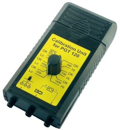
Calibration Unit for PGT 120

Calibration manual for PGT120 with DIP12 switch
1 Preparation
Starting point for all measurements are the following DIP switch settings.
The calibration is performed with the customers test voltage setting (DIP-switch 4 and 5) If desired, the test can be repeated with the other available test voltage settings.
| ON | 5 | 4 | ||||||||||
| OFF | 8 | 3 | 2 | 1 |
2 Wrist strap verification
To check the limits of the wrist strap test connect:
- the middle jack of the calibration unit with the 3 mm snap of the PGT 120 (same symbols ). Use the DK3-socket adaptor which is included.
- the left jack of the calibration unit with the black 4 mm banana socket of the PGT 120. (wrist strap test, same symbols).

Set the marked lever of the rotary switch in succession to the positions mentioned below. Press the left contact electrode for each measurement.

Display LED
3 Footwear test verification (single shoe) - right
To check the limits of the footwear test connect:
- the middle jack of the calibration unit with the 3 mm snap of the PGT 120 (same symbols ). Use the DK3-socket adaptor which is included.
- the left jack of the calibration unit with the red 4 mm socket on the rear side of the PGT 120 (footwear electrode, same symbols).

Set the marked lever of the rotary switch in succession to the positions mentioned below. Press the right contact electrode for each measurement.

Display LED
3.1 DIP-switch settings for upper limit 70 MW
| Switch 3 | Switch 4 |
| ON | OFF |
|
ON |
|
|
|
|
|
|
|
5 |
|
3 |
|
|
|
OFF |
|
|
|
|
8 |
|
|
|
4 |
|
2 |
1 |
Set the marked lever of the rotary switch in succession to the positions mentioned below. Press the right contact electrode for each measurement.

Display LED
4 Footwear test verification (single shoe) - left
To check the limits of the footwear test connect:
- the middle jack of the calibration unit with the 3 mm snap of the PGT 120 (same symbols ). Use the DK3-socket adaptor which is included.
- the left jack of the calibration unit with the yellow 4 mm socket on the rear side of the PGT 120 (footwear electrode, same symbols ).

4.1 DIP-switch setting for upper limit 35 MW
| Switch 3 | Switch 4 |
| OFF | ON |
|
ON |
|
|
|
|
|
|
|
5 |
4 |
|
|
|
|
OFF |
|
|
|
|
8 |
|
|
|
|
3 |
2 |
1 |
Set the marked lever of the rotary switch in succession to the positions mentioned below. Press the right contact electrode for each measurement.

Display LED
4.2 DIP-switch setting for upper limit 70 MW
| Switch 3 | Switch 4 |
| ON | OFF |
|
ON |
|
|
|
|
|
|
|
5 |
|
3 |
|
|
|
OFF |
|
|
|
|
8 |
|
|
|
4 |
|
2 |
1 |
Set the marked lever of the rotary switch in succession to the positions mentioned below. Press the right contact electrode for each measurement.

Display LED
5 Footwear test in series
To check the limits of the footwear test connect:
- the middle jack of the calibration unit with the red 4 mm socket on the rear side of the PGT 120
- the left jack of the calibration unit with the yellow 4 mm socket on the rear side of the PGT 120

5.1 DIP-switch setting for upper limit 140 MW for series
| Switch 8 |
| ON |
|
ON |
|
|
|
|
8 |
|
|
5 |
|
3 |
|
|
|
OFF |
|
|
|
|
|
|
|
|
4 |
|
2 |
1 |
Set the marked lever of the rotary switch in succession to the positions mentioned below. Reset the instrument after each measurement by disconnecting the left wire:

Display LED
5.2 DIP-switch setting for upper limit 70 MW for series
| Switch 3 | Switch 4 |
| OFF | ON |
|
ON |
|
|
|
|
8 |
|
|
5 |
4 |
|
|
|
|
OFF |
|
|
|
|
|
|
|
|
|
3 |
2 |
1 |
Set the marked lever of the rotary switch in succession to the positions mentioned below. Reset the instrument after each measurement by disconnecting the left wire:

Display LED
6 Calibration Unit verification
Recommended calibration cycle: 3 years
To check the resistors, connect a suitable Ohmmeter to the central jack and the left jack of the Calibration Unit and set the marked lever of the rotary switch in succession to the marked positions. The corresponding resistor values and tolerances can be taken from the drawing below.
Also connect the Ohmmeter to the central and right jack of the Calibration Unit. Nominal value must be: 24,4 kW ±1%

7 Device Return and Environmentally Compatible Disposal
The instrument is a category 9 product (monitoring and control instrument) in accordance with ElektroG (German Electrical and Electronic Device Law). This device is not subject to the RoHS directive.

We identify our electrical and electronic devices (as of August 2005) in accordance with WEEE 2012/19/EU and ElektroG with the symbol shown to the right per DIN EN 50419.
These devices may not be disposed of with the trash.