Transforming Technologies Dual Footwear Wrist Strap Tester Model PDT800K User's Manual
Ohm Metrics
Dual Footwear Wrist Strap Tester Model PDT800K

Instruction Manual
Contents
Description
| PDT800 | 1 |
| Features | 1 |
| Front Panel Controls | 2 |
Installation
| Free Standing Assembly | 4 |
| Height Adjustment | 5 |
| Wall Mount | 5 |
| Change Limits | 5 |
Testing
| Wrist Strap | 6 |
| Footwear | 6 |
| 4 Turnstile/Barrier/Gate System | 8 |
| Specifications | 8 |
| Parts Included List | 8 |
| Service and Warranty | 9 |
Description
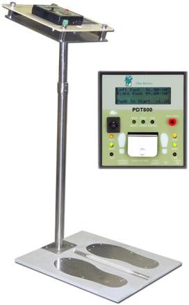
Ohm Metrics Deluxe Combo Wrist Strap and Footwear Tester: Model PDT800
The PDT800 is a comprehensive, accurate tool to fully meet your daily ESD checking needs. Inde- pendently tests the left and right foot and wrist band and an innovative LCD screen will instantly display the test result and the measured resis- tances. The proactive “Near-Fail” indicator alerts the user that the ESD grounding device under test is nearing failure levels. Meets or exceeds the requirements of international standards such as ANSI/ESD S20.20-2007 or IEC61340-2007
Features include:
- LCD display instantly displays the test result and the measured
- “Near-Fail” LED
- Tests both wrist strap and footwear simultane- ously or independently.
- 100% independently test the left-foot and the right-foot.
- Test limits meet USA and European standards; preset with broad test range 100KΩ~1GΩ.
Front Control Panel

- Wrist strap Plug-jack
- Right Foot LED Indicators
- Power Input
- Grounding Jack
- Foot-Plate Wire Jack
- Test Button
- Adjustable Audio Alarm
- Left Foot LED Indicators
- Toggle Switch
- Wrist-Strap LED Indicators
Assembly
The PDT800 has two options for installation: Free- standing installation with a pedestal or wall mounting.
Free Standing Installation
- Remove all items from carton and confirm you have received all items contained in the “Parts In- cluded List” on page 8.
- Remove plastic from the metal sensors of the footplate.
- Thread Cord A through the pedestal with the straight plug emerging from the bottom.
- Unscrew and remove the metal plate on the front of the footplate and set the screws aside.
- Connect the straight plug to underside of footplate. See Image:

- Slide the metal plate removed in Step 3 into the slot on the underside of the footplate.
- Fasten the stand to the footplate with the four shorter screws that where removed earlier.
- Thread CORD A’s right angle plug through the smaller hole on the mounting plate and secure the plate to the top of pedestal with the included screws.

- Attach the four spacer posts to the to the metal plate with a rubber washer between the post and plate.
- Place the tester’s plastic mounting board on the four posts with the rubber washers between the post and the plastic board and secure with screws.
- Locate the AC power cord and Cord B and thread (the ends that fit the jacks on the bottom of the tester) though the large hole in metal plate and the hole in the backing board.
- Connect the three cords to the tester.
- Connect the banana plug of the Cord B to ground.
- Plug in the power cord.

Note: In free standing installation, it is recommended to have the unit against a wall for stability.
Wall Mount
The PDT800 can be mounted on to any flat, stationary surface. Frequently, the unit is mounted on a table or wall
- Secure monitor to a solid wall with screws via the four holes in the corners of the mounting board.
- Connect the footplate and monitor together with the footplate cord like Steps 3, 4, and 5 in Free Standing Place footplate directly un- der monitor
- Connect the Power, Ground and Footplate cords to their proper jacks.
- Connect the banana plug of Cord B to Plug in the power cord.
Change Limits
The high and low limits of both wrist strap and foot- wear can be changed by the DIP Switch located at the bottom of the tester.
- Put all DIP switches to the UP position (0 means Open). Power off tester followed by a power on.
- Set the desirable high limit and low limit of wrist- strap and Then do a power off followed by a power on again.
- To change the low limit resistance for both wrist- strap and footwear: Turn on DIP switch S1 to change the low limit resistance of both wrist- strap and footwear from 1M to 750K ohm.
- “Test Wrist OR Foot” mode: Turn on DIP switch S2 to enable the “Test wrist OR foot” mode. Un- der this mode, the final result will be a PASS if either wrist or feet passed the test. Please note that if any test on wrist or feet is LOW, the final test result will become a FAIL since the LOW test result implies a potential hazard to human body.
- DIP switch S3 controls the high resistance limit of wrist-strap testing as following:
|
S3 |
High Limit Resistance |
|
OFF |
10M |
|
ON |
35M (Default) |
- DIP switch S4 controls the low resistance limit of footwear testing as following:
|
S4 |
Low Limit Resistance |
|
OFF |
100K |
|
ON |
1M (Default) |
- DIP switch S5 and S6 control the high resistance limit of footwear testing as following:
|
S5 |
S6 |
High Limit Resistance |
|
OFF |
OFF |
10M |
|
OFF |
ON |
35M |
|
ON |
OFF |
100M(Default) |
|
ON |
ON |
1G |
Testing
After the PDT800 is powered on, a short beep will sound and all the corresponding LED’s turn on. Now the tester is ready to be used.
Use the Toggle switch on the left-upper side of the tester to select the test you desire:
| UP | Tests Wrist Strap Only |
| Down | Tests Footwear Only |
| Middle | Tests Both Footwear and Wrist Strap |
Wrist Strap Only Testing
- While wearing a wrist strap, insert the banana plug end of cord in the jack labeled “WRIST STRAP”
- Toggle switch up for “WRIST STRAP”.
- Press and hold the test button.
- A short audible beep and a green LED labeled “PASS” lights up indicating that the wrist strap and cord are functioning properly.
- If the red LED and a long beep activate than the wrist strap failed “LOW”.
- If the yellow and green LED lights, along with two short beep sounds, than the wrist band “FAILED HIGH”.
Footwear Testing
The PDT800’s duel footwear sensors allows for simulta- neous testing of each foot independently. The left foot’s status is indicated with the LED lights on the left side and the right foot is indicated on the right side of the monitor.
- Turn the toggle switch located down to test “FOOTWEAR”
- Place feet onto silver sensors of platform.
- Press the test button and hold for 2-3 seconds
- The green LED labeled “PASS” indicates that the grounding device is functioning properly.
- The red LED labeled “LOW” the device is nearing failing levels and should be repaired or re- placed.
- The yellow LED labeled “HIGH” indicates the de- vice has failed and is not longer grounding the opera- This indication is accompanied by audible alarm.
Turnstile/Barrier/Gate System:
The PDT series testers have a built in N/C N/O switch used with doors or turnstiles where a positive test allows the person to move through. The relay has contact rat- ing of 1A 30VDC maximum, with the center contact as COMMON contact and the left contact as NC(normally close) and the right contact as NO(normally open). These are the inputs that are used to connect the device you want to trigger.
Product Specifications
|
ESD Footwear Test: |
100% Left/Right Foot Independent Test- ing |
|
ESD Wrist-Strap Test: |
Traditional Single Wrist-Strap |
|
Test Modes: |
WS only / FW only / Both WS and FW |
|
High/Low Test Limits : |
Factory default: Wrist 1MΩ~35MΩ / Foot 1MΩ~100MΩ. Accept customer pre- set at factory; range is 100KΩ~1GΩ. |
|
Test Push Button: |
Ergonomic Metal Plate for Reliable/ Durable Operation. |
|
System Built-in Relay: |
Dry Contact Control, 1A 30VDC |
|
Special Reminder: |
Indicate “Near-Fail” Test Result on LED |
|
Input Voltage: |
100-240/VAC, 50/60Hz, 1A |
|
Operation Temperature: |
0°C ~ 40°C, for Indoor Use Only |
|
System Dimension: |
140x125x33 mm (L x W x H) |
|
Dual Independent Footplate Dimension: |
480x403x25 mm (L x W x H) |
Parts Included List
- PDT800 tester
- Foot plate
- Pedestal
- AC adapter
- 2 connection cords.
- Posts and Screws
 Cord A Cord A |
 Cord B |
Service and Warranty
Transforming Technologies, LLC provides a limited war- ranty for the Model PDT800. All new products are guaran- teed to be free from defects in material and workmanship for a period of one (1) year from the date of shipment. Li- ability is limited to servicing (after evaluating, repairing or replacing) any product returned to Transforming Technolo- gies. The company does not warrant damage due to mis- use, neglect, alteration or accident. In no event shall Transforming Technologies be liable for collateral or conse- quential damages. To receive service under warranty, please contact Transforming Technologies Technical Sup- port.